Culvert
Culverts come in two different types: User specified QH relations and Calculated QH relations. The two types are described below.
User specified QH relations
A culvert with user specified QH relations is described by different algorithms for critical flow, drowned flow and full-pipe flow. The full-pipe flow case is divided into free outflow, drowned flow and submerged flow. A QH relationship must be input covering all cases of critical outflow flow and free outflow from the culvert.
Critical discharge is determined by a weir type formulation when the inlet is free, and an orifice type formulation when the inlet is submerged.
The flow through culverts is described using the following assumptions (1): The culvert is horizontal, and the friction loss inside the culverts is negligible.
Note! the friction losses can be incorporated into the QH relationship as discussed below.
Six different flow situations are distinguished depending on the upstream and downstream water levels. In the mathematical formulation these situations are reduced to four standard cases: zero flow, critical flow, drowned flow and submerged flow. The 6 different flow situations are presented in the user specified culvert flow regimes.
In the case of full-pipe flow the actual flow situation is first determined using the user specified culvert flow regimes. For case iv) the user specified QH relation is used, while for case v) and vi) the coefficients in the energy equation are determined by setting hs = HSTMAX where HSTMAX is the highest elevation-width relationship specified, and the width bs = 0 in the structures equation for drowned flow, where hs is the water elevation at the structure and bs is the structure width.
The transition from case iv) to v) is handled as follows. The two discharges Qiv and Qv are calculated using the assumptions of case iv) and v), respectively. If Qv > Qiv then flow case iv) is chosen.
In this figure the following relationships apply:
i) zero flow: Qs = 0
ii) and (iv): critical flow and submerged flow with free outlet:
- Qs = Q(h1) (according to tabulated input function)
(iii), (v) and (vi): drowned flow, submerged flow with both backwater influence from outlet and where the downstream water level exceeds the top of the culvert:
Equation: Energy balance for submerged culvert flow accounting for contraction loss.
The losses due to friction along the length of a pipe can be incorporated into the QH relation during the critical flow period, and into the contraction and expansion loss coefficients during drowned flow. The Manning equation is typically used for this purpose.
If the culvert is a structure in a composite structure, the altered characteristics should be incorporated by the user into the QH relation.
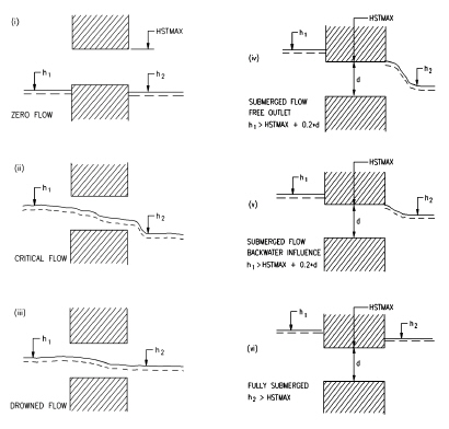
Figure: User specified culvert flow regimes.
Calculated QH relations
- The Culverts, QH Relations Calculated structure is a more advanced treatment of the flow through a culvert than the Culverts, User Specified QH Relations structure described in the above section. The main differences are:
- The QH relationships are calculated by the MIKE 1D engine.
- The culvert can be assigned a length, friction coefficient, slope and bend loss coefficient in addition to the conventional parameters.
- The culvert cross section can be defined by a standard shape (e.g. circle or rectangle). A user defined cross section can also be provided as a depth versus width table, or an existing cross section can be chosen from the database.
The structure has been designed for modelling culverts of any shape, length or slope. All flow conditions are modelled, including full submergence, partial submergence, critical inflow and outflow, orifice flow and full culvert flow with a free outflow.
Specification
The culvert cross section shape is specified as either a standard shape (rectangle, circle), an irregular shape defined as a (depth or level)/width relation or by a cross section from the cross section database. Other required parameters are:
- Culvert length (m)
- Upstream and downstream invert levels (m)
- Number of parallel culverts
- Friction coefficient (Manning's n)
- Valve regulation switch which may be set as
- Flow only in negative direction (decreasing chainage)
- Flow in both directions (none)
- Flow only in positive direction (increasing chainage)
- Closed/open cross section switch
- Coefficients in both positive and negative flow directions for:
- Inflow losses (typically 0.5)
- Outflow losses (typically 1.0)
- Bend losses (straight culvert would be 0.0)
- Free overflow correction coefficient (typically 1.0)
Flow descriptions
The flow through a culvert can be broadly classified into three areas for computational purposes: zero flow, upstream controlled flow, and downstream controlled flow. - The flow conditions mentioned below are illustrated in the calculated culvert flow conditions
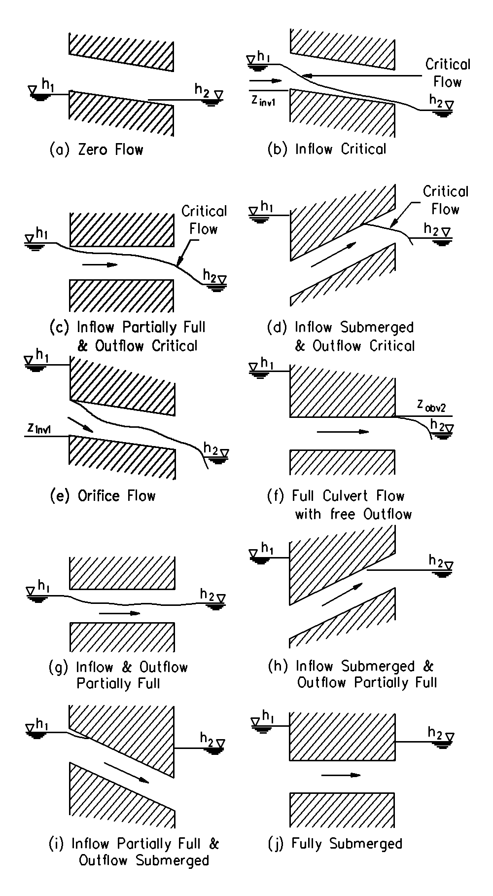
Figure: Calculated culvert flow conditions. Zero flow. The zero flow condition occurs when one of the following conditions is present:
- The culvert is dry
- The valve regulation switch is set to negative and the flow would be in a positive direction if the valve was open.
-
The valve regulation switch is set to positive and the flow would be in the negative direction if the valve was open. Upstream controlled flow. The upstream controlled flow condition occurs when the downstream water level has no influence on the discharge through the culvert. The discharge is therefore solely a function of the river water level at the culvert inlet, h1, and can be tabulated (QH relation) prior to the simulation, minimizing the computational load during the simulation. The flow conditions modelled are:
-
Critical inflow
- Partially full inflow and critical outflow
- Submerged inflow and critical outflow
- Orifice flow at inflow with free outflow
- Full culvert flow with free outflow
Expressions for the loss coefficients, momentum equation coefficients, upstream controlled flow (critical inflow or outflow, orifice flow at inflow and full culvert flow with free outflow) and downstream controlled (submerged) flow are described in detail in Appendix B.1. The transition between upstream and downstream control is also described in Appendix B.1. Downstream controlled flow. Downstream controlled flow (or submerged flow) occurs when the downstream water level imposes a constraint on the flow through the culvert. The calculation of discharge is performed during a simulation because the discharge is a function of both upstream and downstream water levels and therefore is not practical to tabulate. The flow conditions modelled are:
- Partially full inflow and outflow
- Submerged inflow and partially full outflow
- Partially full inflow and submerged outflow
- Fully submerged
Construction of QH relationships
The two steps are given here.
The QH relations (one for each flow direction) are presented for verification under the QH relations tab. For convenience, the relationships are given as the water depth, y1, versus Q, not water level, h1 versus Q. The value of h1 is equal to the culvert invert level plus y1.The values of area and hydraulic radius are shown under the Hydraulic Parameters tab for verification purposes only.
Calculation of the QH relations for upstream controlled flow is a two-step process which is described here.
First, the hydraulic parameters: area, hydraulic radius and conveyance flow, are tabulated for depths ranging from zero to full culvert depth. A cosine function is used for setting the tabulated depth values in order to give more detail at the bottom and top of the culvert cross sections where the variation of area and hydraulic radius is very non-linear.
If an irregular cross section shape is specified, and if the depth or level/width table has the same number of rows as the specified number of QH relations, the depths in the depth (or level)/width table are used for calculating the hydraulic parameters, otherwise the cosine function is used. This provides the opportunity for the user to specify the depths at which the hydraulic parameters are to be calculated.
Second, h1 is calculated for critical depths ranging from zero to that at 95% of the full culvert area. Whether the flow is critical at the inflow or outflow is determined according to the description above.
An iterative procedure is used to calculate h1 since the contraction loss coefficient z1, and the inflow river cross section area A1 are functions of h1.
At the start of the simulation a check is made to ensure that the distance between the upstream and downstream cross sections is bigger than the length of the culvert. The cross sections must also be located within a distance which is smaller than the user-defined maximum grid-spacing ('Maximum dx') for the branch in question. The Q/h relations cannot be calculated unless cross sections are defined. If this is not the case an error message will be returned. Ideally, the upstream and downstream cross sections should be located immediately upstream and downstream of the culvert.
When critical flow can no longer occur because of submerged inflow and/or outflow, the flow condition will be either orifice flow or full culvert flow. The QH relations continue to be constructed by calculating the discharge for increasing values of h1. The maximum value of h1 in the tabulation is defined as the greater of (a) the maximum depth in the adjacent cross section, and (b) five times the culvert depth above the invert.
If the inflowing water level exceeds the maximum h1 value during a model simulation, a linear extrapolation is made based on the last two pairs of values in the QH relations.
Iterative procedures are also necessary for Qo (orifice flow, Qo) and Qp (primed flow, Qp). The discharge adopted is taken as the minimum of Qo and Qp. However, once Qp is lower, full culvert flow occurs (i.e. Qp < Qo), and the culvert is assumed to remain flowing full, i.e. the culvert is “primed”.
For each iterative procedure mentioned above, convergence usually occurs in two to three iterations except in the case when the culvert inflow cross section area, \(A_{s_{1}}\) and A1 are of similar magnitude, i.e. as z1 approaches zero. A maximum number of one hundred iterations is allowed, and if exceeded a warning message is given. The QH relations will be calculated, but the user should check the adjacent cross sections description and the culvert specifications.
If \(A_{s_{1}}\) is greater than A1 or the Q values are decreasing with increasing h the calculation of the QH relations is suspended and warning messages are returned. The point in the QH relations where the problem occurred can be observed by inspecting the QH tables.
Simulations will not be possible unless the QH relations have been successfully calculated.
Note that if the Topo ID or the upstream and downstream cross sections are changed, the QH relations must be recalculated.
Closed/open section switch
A culvert can be modelled as an open section by setting the closed/open switch. An example where this may be used is a “long” weir where the friction along the length of the weir is of importance and/or the flow areas at the entrance and exit are significantly different.
If set to open, the culvert will never run full or even partially full, therefore only those flow conditions which represent a free water surface are modelled. When the water level is higher than the soffit the hydraulic parameters are calculated based on a cross section extended vertically upwards with a width equal to that at the soffit. For example, in the case of a rectangular cross section the height value would essentially be redundant as the cross section will be modelled as an open cross section of constant width.
In the case of a circular cross section, the switch is invalid and the culvert will be assumed closed. For culverts defined by a cross section the switch is invalid as well, and the parameter has to be defined in the cross section module.
Flooded areas of adjacent h-grid points
The flooded or storage areas of the two adjacent h-grid points are reduced by half of the culvert length multiplied by the cross section width. In effect the culvert is considered to have a zero contribution to the storage of the system. In the rare case where the storage within the culvert is significant compared to that in the reach, the flooded areas at the adjacent h-grid points should be adjusted using the additional flooded area parameter, see Section 3.7 Flooded Areas and Relative Resistance (p. 47).
Velocities
The velocity through a culvert is calculated in one of three ways: 1) as Q/Ac in the case of critical inflow or outflow, where Ac is the critical flow area, 2) as Q/Afull in the case of orifice flow or full culvert flow, where Afull is the full cross section area of the culvert, or 3) as \(Q/S_{S_A}\) in case of downstream controlled flow. In the latter case, \(Q/S_{S_A}\) is equal to the mean of \(Q/S_{S_{1}}\) and \(Q/S_{s_{2}}\) , the culvert inflow and outflow cross section areas, respectively.
-
Chow, V.T.: Open-Channel Hydraulics. McGraw Hill, 1959. ↩