Overflow Formula (MIKE+ Broad Crested Weir)
The standard formulations for Overflow Formula are established automatically on the basis of the weir geometry and the user specified headloss and calibration coefficients. Different algorithms are used for drowned (or submerged) flow and free overflow, with an automatic switching between the two.
Both algorithms assume a hydrostatic pressure distribution on the weir crests (constant water depth on the crest).
In MIKE+, the standard weir type is called a Broad Crested Weir. In the 1D engine, this standard MIKE+ structure is called Overflow Formula.
Free overflow formulation
The MIKE 1D engine provides two different methods for the computation of the free overflow:
- Flow computation based on the energy loss coefficient and weir orientation.
- Flow computation based on a standard rectangular overflow weir formula with user-specified discharge coefficient.
Energy loss coefficient formulation
In case of a free overflow, the water depth above the weir crest will be equal to the critical water depth. The energy loss occurs depends on the structural configuration. The overflow situation is shown in the free overflow
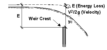
Figure: Free overflow.
In the critical flow cross section, the Froude number Fr is equal to 1, and the critical flow condition can be written as:
Equation: Critical flow condition where Froude number equals unity at the overflow section.
where:
- v — mean flow velocity, [ms-1]
- yc — critical depth, [m]
- g — 9.81 [ms-2] Conservation of energy between the upstream and critical cross section yields:
Equation: Energy conservation equation between upstream and critical cross section.
with:
Equation: Energy loss coefficient dependent velocity head at broad crested weir.
where:
E = energy level at the cross section just upstream the structure, [m] DE = Entrance energy loss, [m] Kc = Energy loss coefficient
Based on the energy conservation and critical flow principles, discharge over a plane overflow having a structure width B [m], is calculated for a weir orthogonal to the flow axis (90o), as:
Equation: Discharge over orthogonal broad-crested weir from energy conservation and critical flow.
and for a 'side' overflow weir (0o):
Equation: Discharge over a broad-crested weir with side overflow orientation.
where:
- H — water depth above the weir crest level, [m]
- Kc — energy loss coefficient associated with the outlet head-loss specified for the weir node.
This corresponds to the standard overflow formula for a rectangular notch:
Equation: Overflow formula for broad-crested weir with rectangular notch using discharge coefficient.
where Cd is a discharge coefficient, expressed for an orthogonal weir as:
Equation: Discharge coefficient for orthogonal weir as function of crest shape factor.
and for a 'side' overflow weir:
Equation: Discharge coefficient for side-overflow weir as a function of contraction parameter.
E.g., this method if used with Kc = 0.5 (sharp-edged outlet), is equivalent to a standard weir formula with Cd = 0.7589 and Cd = 0.4582 for orthogonal and for side weir, respectively.
The side overflow yields a smaller discharge for the same overflow level, because in this case the kinetic energy of the approaching flow is excluded from the computations.
User-specified discharge coefficient
If the method with default energy loss coefficient is not applicable for a particular weir, the standard overflow formula Equation the overflow formula for broad-crested weir with rectangular notch using discharge is applied with a user-specified “level” discharge coefficient CH = 2/3Cd, which gives:
Equation: Discharge over a weir from the standard overflow formula with specified discharge coefficient.
This implies that the headloss coefficient specified for the weir node and the weir orientation are ignored in the weir computation.
Submerged overflow
Discharge across a submerged weir is calculated using the same critical depth formulation as above for a free overflow, except that the head driving the flow is expressed as the difference between the upstream and downstream water surface elevations. See figure the submerged overflow.
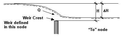
Figure: Submerged overflow.
The submerged weir flow is then (with user-specified “level” discharge coefficient) approximated as:
Equation: Submerged weir discharge using user-specified level discharge coefficient.
or with energy loss coefficient, for orthogonal overflow weir:
Equation: Discharge over orthogonal broad-crested weir with submergence correction factor.
and for a 'side' overflow weir (0o):
Equation: Discharge over a broad-crested weir with submerged tailwater correction factor.