Resistance Specification
Flow resistance, in river applications called bed resistance, defines how easily the water flows through a cross section. The resistance depends on a number of physical characteristics; for instance on the material of the cross section (plastic/concrete), the vegetation (grass) and variations in shape along the reach that are too small to be represented in the model.
There are several resistance formulations
- Manning’s M/n
- Chezy
- Darcy-Weisbach
- Colebrook-White for circular pipes
- Hazen-Williams
Each formulation enters the flow equations in the momentum equation, Equation (4.1b), as the resistance term. The actual implementation of the resistance term varies with the formulation, details are given in Section 4.3.
The formulations are introduced in Section 3.3.3 to Section 3.3.7
In real world situations the wall/bed roughness and thereby the resistance number varies with the water depth, due to changes in material, vegetation, erosion, sediment deposits etc. over the cross section. The resistance also depends on the flow conditions that the cross section has been exposed to during its lifetime.
The engine supports the following variations of the resistance number:
- Constant, i.e. no variation
- Depth-variable
- Distributed
- Flow bank zones
- Multi zone (triple zone)
The depth variabilities are discussed in Section 3.3.8 to 3.3.11.
Relative resistance numbers
Resistance numbers for a cross section can be specified relative to the resistance number in the HD parameters. Then the resistance formulation will follow the formulation set in the HD parameters.
Relative resistance numbers higher than one always correspond to higher physical resistance, i.e. independent of the choice of resistance number type in the HD parameters.
The effect of the relative resistance values on the hydraulic parameters in the processed data is dependent on which type of hydraulic radius is used. For details, see Section 3.4.2.
Calibration of resistance numbers
Values for the resistance numbers should be determined through model calibration where possible, or based on other calibrated models with similar topographical characteristics. A rough guide to values of Manning’s n can be found in most publications dealing with open channel hydraulics, e.g. 1.
Note that resistance numbers from a calibration based on a resistance radius, R*, should not be directly transferred to a model using the hydraulic radius, Rh, and vice versa. It is, therefore, not recommended that a combination of resistance and hydraulic radius be used for different cross sections in a model setup, as this could lead to different calibrated resistance numbers between similar reaches, and other problems. The formulations for resistance and hydraulic radius is discussed further in section 3.4.2.
Manning formulation
The application of Manning's formula uses a friction slope:
Equation: Friction slope in Manning resistance formulation as a function of discharge and flow properties.
with the friction factor:
Equation: Manning friction factor relating resistance to Manning coefficient, flow area, and hydraulic radius raised to 4/3 power.
where M is the Manning resistance number, A~fl ~the flow area, and R the hydraulic radius. Conveyance is defined as
Equation: Conveyance as the product of Manning coefficient, flow area, and power of hydraulic radius.
The unit of the Manning M is \(m^{1/3} / s\). The Manning number, M, is equivalent to the Strickler coefficient. It is the inverse of the Manning n, i.e.
Equation: Manning M coefficient defined as the reciprocal of Manning n roughness.
The value of n is typically in the range 0.01 (smooth) to 0.1 (thickly vegetated/very rough bottom). The corresponding values for M are from 100 to 10.
Chezy formulation
The application of the Chezy formulation uses the friction slope:
Equation: Friction slope using Chezy formulation with dimensionless resistance factor.
with the friction factor:
Equation: Friction factor derived from Chezy coefficient and hydraulic properties.
where C is the Chezy resistance number, Afl the flow area, and R the hydraulic radius. Conveyance is defined as
Equation: Conveyance for a cross-section using Chezy resistance formula.
The unit of the Chezy number C is shown in the following formula:

Figure: Unit of the Chezy resistance number in SI units.
The Chezy coefficient is related to the Manning coefficients by (2):
Equation: Relationship between Chezy and Manning resistance coefficients through hydraulic radius.
The difference between the Chezy and Manning descriptions is the power of R. The Manning description gives a formulation where the value of M can, in general, be considered as independent of the depth of water, while for the Chezy formulation the value of C varies with the depth, as implied by Equation the relationship between Chezy and Manning resistance coefficients through hydraulic.
Darcy-Weisbach formulation
The Darcy-Weisbach resistance number is specified in the form of an equivalent grain diameter, ks.
The engine converts the Darcy-Weisbach resistance number to a Chezy resistance number, and uses the Chezy formulation during simulations. The relation between the Chezy C and the dimensionless Darcy-Weisbach resistance number \(\lambda\) reads:
Equation: Relation between Chezy resistance coefficient and Darcy-Weisbach friction factor through gravitational acceleration and water depth.
The dimensionless \(\lambda\) relates to the grain diameter, ks as follows:
Equation: Nikuradse-type resistance correlation relating Chezy coefficient to relative roughness.
where R is the hydraulic radius. With some rearrangements it becomes:
Equation: Chezy resistance coefficient derived from the Colebrook-White formulation.
The additional resistance due to vegetation can be entered in the Cross Section Editor and will impact the processed data.
Colebrook-White formulation for circular pipes
In 1939, Colebrook and White derived an approximate formula which unifies the description of the turbulent flow in both rough and smooth circular pipes. This formula is extensively used for the computation of flow resistance in predominantly full-flowing pipe networks.
According to Colebrook and White, the friction factor f is computed iteratively, using one of the several formulations known from the literature. The formula implemented currently reads:
Equation: Colebrook-White implicit friction factor equation for pipe flow resistance.
where:
- k — the equivalent wall roughness [m]
- R — the hydraulic radius
- Re — the Reynolds number cw1, cw2, cw3, cw~4 = ~empirical constants.
The default values of the constants cw1-cw4 are:
cw1 = 6.4 cw2 = -2.45 cw3 = 3.3 cw~4 ~= 1.0
In MIKE+ (Collection System), the default values can be modified through DHIAPP.INI file. See Appendix D.3.
The actual friction slope is calculated by using the following relation:
Equation: Colebrook-White friction slope formulation converting resistance number to energy loss rate.
The Colebrook -White friction resistance can only be used if an implicit friction formulation is activated.
Use of the Colebrook-White formula must be restricted to circular reaches only. Also, the Colebrook-White formula is fully valid for full-flowing pipes.
Hazen-Williams formulation
The Hazen-Williams equation is an empirical formula which relates the flow of water in a reach with the physical properties of the reach and the pressure drop caused by resistance. It is used in the design of water pipe systems such as fire sprinkler systems, water supply networks, and irrigation systems. The Hazen-Williams equation has the advantage that the resistance number C is not a function of the Reynolds number, but it has the disadvantage that it is only valid for water and it is not able to account for temperature or viscosity.
Equation: Discharge from the Hazen-Williams empirical resistance equation.
where:
- k — is a conversion factor for the unit system (k = 1.318) for US customary units, k = 0.849 for SI units)
- C — is the roughness coefficient
- R — is the hydraulic radius
- S — is slope of the energy line (head loss per length of pipe) The slope of the energy line S is used as the friction slope \(I_f\).
Depth-variable resistance number
The engine accepts a specification of a non-linear variation of the resistance number, based on a relative water depth. Three parameters define the resistance number variation: a bottom value, a full flow value and a non-linear exponent. Intermediate values are calculated by the expression, here for Manning’s M:
Equation: Non-linear variation of Manning resistance number with relative water depth.
where:
Mact = calculated resistance number, Mbot, Mtop = resistance numbers at bottom/top of cross section, exp = variation exponent, y = the current water depth in the cross section D = Height of cross section.
The formula is used for relative depths h/D in the interval 0.0 - 1.0. For relative depth > 1.0 the actual value is set to the Mtop value.
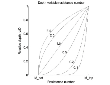
Figure: Relative variation of the Manning number with relative depth.
The variation between Mbot and Mtop is controlled by the “variation Exponent”. The variation of the resistance number in relative terms is illustrated in the relative variation of the Manning number with relative depth.
In MIKE+ (Collection System), the Manning number variation is specified through the ASCII file *.ADP. The specified Manning numbers in the *.ADP file must follow the selected option for the Manning number convention. Syntax of the format of the *.ADP files must be as shown in the 'DHIAPP.INI and *.ADP Reference Manual'.
The lines of the *.ADP file related to the Manning number variation may be easily compiled by copy-and-paste operations from the MOUSE650.OUT file. This ASCII file is generated by every computation with the MOUSE Pipe Flow Model.
Before using the *.ADP file, the Manning number parameters for the selected lines must be modified, i.e. values for bottom and top of pipe Manning numbers and possibly the variation exponent must be adjusted for the pipes or canals where varying Manning numbers are to be used.
Distributed resistance numbers
For user specified cross sections, the resistance number can be specified on each (x,z) point of the raw data. The resistance number entered on data point number i will be applied on any volume above the line segment between data point i-1 and i.
The processing of the raw data will create the resistance numbers actually used by the engine, see Section 3.4 for details.
Flow bank zones
An open cross section can take flow banks into consideration when calculating the resistance number. In this case you must specify the resistance numbers for the left bank, the right bank and the main river (called “low flow zone”).
The left bank resistance number is used between marker 1 and 4, and the right bank resistance number is used between marker 5 and 3. In the remainder of the cross section, the main resistance number is applied. If marker 4 or 5 is not set, the left or right bank resistance number will not be used.
The flow zone specification is an alternative way of specifying distributed resistance numbers.
Multi zone resistance specification
It is possible to specify a set of vertical zones based on either water depth or water levels, where the resistance number is constant within each zone.
The multi zone resistance parameters are specified in the HD Parameters.
In MIKE 11 it is called triple zone, since 3 zones can be specified. The zone separators are based on water levels. These are specified in the HD Parameter Editor, under the “Bed Resist” tab.