Some Special Techniques
Expanding node covers (Surface flooding)
This technique is used to simulate manholes and basins that flood surrounding surfaces, with the water assumed to re-enter the collection system network after the flooding event.
If the water level in an open manhole or a basin reaches ground level, an artificial inundation basin is inserted above the node. The surface area of this artificial basin is gradually increased from the top of the manhole or the basin, thus simulating the surface inundation. When the outflow from the node becomes greater than the inflow, the water stored in the inundation basin re-enters the system.
The inundation basin is simulated by assuming an expansion from the manhole or basin. The rate of expansion is controlled by a parameter specified in the MIKE 1D engine configuration tab. Different parameter values are applied to manholes and basins. The manhole expansion parameter is called, "Manhole cover expansion coefficient", and the default value is 1000. The basin parameter is called, "Basin cover expansion coefficient", and the default value is 1. The basin parameter also controls the expansion of inundation basin for soakaways. The effect of the default values is that the manhole inundation basin increases to 1000 times the manhole area, while the basin area does not become larger than the top of the basin geometry curve.
Expansion is assumed to take place over a vertical distance of 1 metre. For manholes, the starting elevation of the expansion is specified in the MIKE 1D engine configuration tab, using the parameter, "Node cover start level. The default value is 0.25m below ground level. For basins and soakaways, the expansion begins at the top of the geometry curve.
Mathematically, the expanding cover enters the node equations (see Section A.2.2) only through the calculation of the surface area in the node. For the expanding manhole cover with default expansion coefficient, the surface area is
Equation: Flow area for an expanding node cover, capped at a minimum and growing exponentially with water level above ground.
where \(A_{fl,node}\) is the surface area just below the cover and \(H_{gl}\) is the ground level.
When the water level in the node increases and is above ground level, it is assumed that during a time step, the surface area in the basin is calculated using the water level from the start of the time step. A situation like this is shown in the simulation of surface flooding. If the water level passes through the transition region between the actual manhole or structure and the artificial basin. This leads to generation of water. In the simulation of surface flooding the shaded area illustrates the generated volume of water.
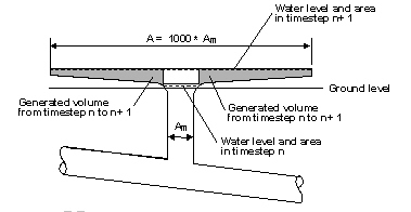
Figure: Simulation of surface flooding showing generated volume in the transition region between the manhole and artificial basin.
When the increase of the water level during a time step is relatively small, then the generated water volume is negligible. If the water level is changing rapidly, the generated volume of water is important. Therefore, MIKE 1D will calculate the difference in water volume and correct the mass balance accordingly in the following time step.