MIKE 1D result files and results
If a warning or error occurs during initialisation or simulation, a log-file is created next to the project like with the MOUSE engine. The log-file is called Simulation ID + Scenario ID + _ErrorLog.html. However, it should be noted that the file is created also if no errors occur.
Further, a summary file is created after end of simulation containing similar information as for the MOUSE engine. The summary-file is named Simulation ID + Scenario ID + _Summary.html.
The result files from MIKE 1D all have the extension .res1d regardless of the content. This is consistent with MIKE's other engines, but different from the MOUSE engine where the extension denoted the content.
The name of the result file follows the common principle from MIKE URBAN, e.g., Simulation ID + Scenario ID, however a further suffix of the name now denotes the content. As an example, the result file from a runoff simulation will have the suffix "RR" and hence the result file name could become CityABaseRR.res1d.
Table: Result file types and the suffixes that denote their content.
| File Type | Suffix |
|---|---|
| Runoff result file | *RR.res1d |
| Catchment discharge result file | *CatchmentDischarge.res1d |
| Catchment discharge AD results | *CatchmentDischargeAD.res1d |
| RDI Additional output result file | *Add.res1d |
| Additional output as specified in the dhiapp.ini file | *ADDOut.res1d |
| User specified result file | UserSpecified."resultSpec.MUID".res1d |
Results from a MIKE 1D simulation can be viewed directly in MIKE URBAN. When loading a .res1d file, the user experience is like loading a PRF-file.
In MIKE View, one thing to note is that when selecting results the distinction between pipes and nodes is in the Data Type and not in a separate filter, e.g., the water levels in pipes are found under the data type Water level and the water levels in nodes are found under Water level Node.
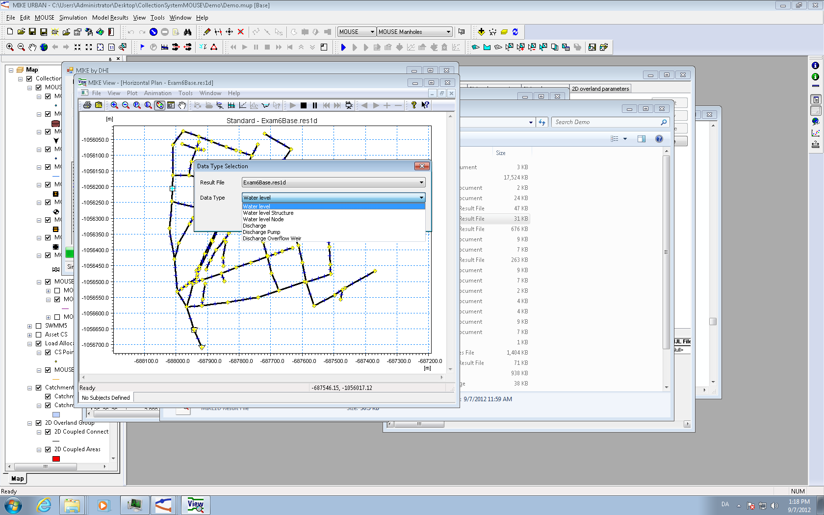
Figure: Selecting a result data type in MIKE View, where pipes and nodes are distinguished by data type.
When selecting using the map, the user should directly select the grid-point on the link which should be plotted. The same method as used when selecting results in MIKE URBAN.
When selecting in a list it should be noted that some results (e.g., catchments or structures) will have a suffix indicating the nature of the result. For example, an output file from a combined runoff with RDI + Kinematic Wave (B) will have three results per catchment (as for the existing engine) where the suffix of the catchment is respectively "- RDI" and "- Kinematic Wave (B)".