River End/Urban Outlet links
A river end or an urban outlet coupling link exchanges water between the end of a river (or an outlet of an urban model) with a 2D surface model, which is typically a MIKE 21 FM model.
From a modelling point of view, the end of the river (or urban outlet) is set up as a water level boundary condition in the 1D model, and the corresponding location is added as a source/sink in the surface model. The exchange mechanism is quite straightforward and can be explained in the following way: if the last computational node of a river node reports a discharge q, that means that a flow q is leaving(entering) the 1D model at the branch end, therefore, the coupling engine will naturally assign an equivalent coupling discharge q into(out of) the surface model, maintaining the mass balance of the model.
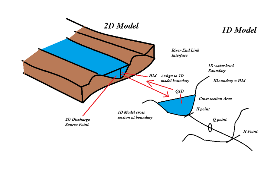
Figure: Conceptual diagram of a River End link.
The modelling of a river-surface coupling with a river end link requires both a surface and a river model, a specification of the coupling link, and a coordinated way to run the time steps of each model, such that the coupler can keep track of the exchange interactions in the model.
The calculation sequence at a River End or Urban Outlet link shows how this is properly done: at the beginning of the simulation, the initial water level at the link location in the 2D surface model is computed (h2D). This value is extracted by the coupling engine and passed to the 1D model, making a water level assignment to the 1D water level boundary. The coupling engine then instructs the 1D engine to perform a time step simulation and after this is done, the coupling engine extracts the discharge value q1D at the link location. Since the link location is at an end of the river, this value represents the discharge being exchanged with the 2D model. This discharge is added to the surface model as a source/sink discharge at the link location in the MIKE 21 FM model. The discharge q1D is distributed into one or more element faces in the 2D model and thus, from a MIKE 21 FM point of view, the link functions as a source boundary condition. The coupling engine then instructs the 2D surface model to perform a time step and the coupling engine extracts and passes the water level again, and the process continues for each time step of the coupled simulation.
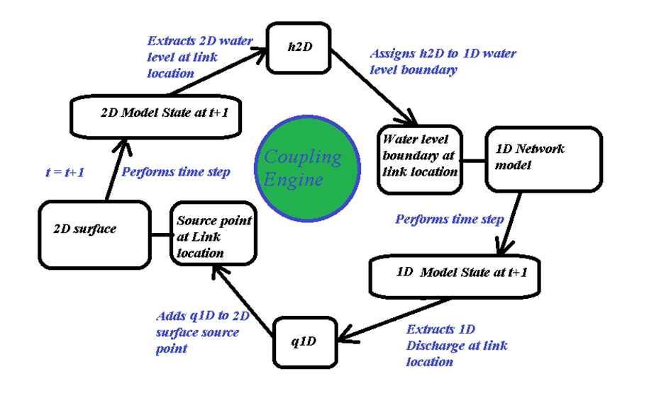
Figure: Conceptual diagram of the calculation sequence at a River End or Urban Outlet link.
Discharges can be positive or negative, and the sign depends on the perspective of the model in question. A positive discharge from the 1D perspective means that water is leaving the river end (or urban outlet) and spills into the 2D model, whereas that same discharge would be considered negative from the perspective of the 2D model.