Boundary conditions
Boundary conditions work the same way in MIKE 1D as in the MOUSE engine with one exception. In MIKE 1D, all catchment-related boundaries are calculated with the runoff simulation and all network related boundaries are calculated with the network. This means that the catchment discharge specified under MOUSE > Boundary Conditions > Catchment Loads… will be included in the runoff simulation.
In the MOUSE engine, catchment discharges were included in the network simulation by using a catchment load referring to a catchment boundary. This functionality is discontinued in MIKE 1D, and a warning will be issued that these boundaries are ignored in a network simulation.
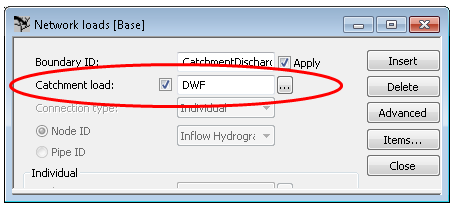
Figure: A catchment load referring to a catchment boundary in the Network loads dialogue.
When using catchment discharge in MIKE 1D everything is configured in the GUI as previously in the catchment load dialogue.
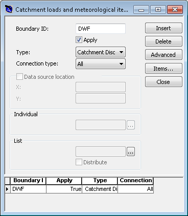
Figure: Configuring catchment discharge in the catchment load dialogue.
After end of the simulation, two result files will be created: one that contains the runoff and one that contains the catchment discharge. Both the runoff result file and the catchment discharge file should be attached as a boundary condition (either on the simulation dialogue or in the network loads).
On the simulation dialogue, both the runoff and catchment discharge file are included on the network parameter tab under Network load input.
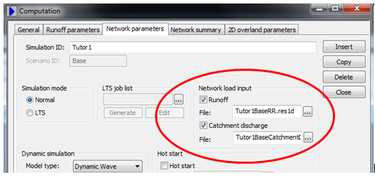
Figure: Attaching the runoff and catchment discharge result files under Network load input.
Special notice should be made for setups which only contain catchment discharge and not rainfall runoff. For the MOUSE engine, a network simulation was needed due to the functionality of the catchment loads in the network loads, but for the MIKE 1D simulation a runoff (catchment) simulation should be run first to produce the catchment discharge result file, followed by the network simulation.
If Transport (AD) is enabled in a setup containing catchment discharge, and there are component items on the catchment discharge load boundaries, a catchment discharge AD result file is created. This catchment discharge AD result file must be added as a network load boundary item to include catchment discharge component loads in the network simulation.