Including Boundaries in the Equations
The following three types of boundary conditions can be applied:
- Water level as a function of time
- Discharge as a function of time
- A tabulated relation between water level and discharge (Q/h boundary)
Each of the boundary types is taken into account by using a different node equation.
Water level as a function of time
In this case the water level in the node at time step n+1 simply becomes the value of the user-specified boundary at time step n+1 (\(H_{boundary}^{n + 1}\)) i.e. in the relevant equation (or row) in the node matrix only the diagonal and the right hand side coefficient are different from zero, and equals respectively 1 and \(H_{boundary}^{n + 1}\).
Discharge as function of time
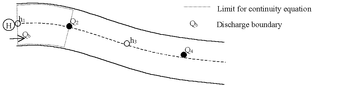
Figure: Reach with discharge boundary.
In this case a local continuity equation covering the area indicated in the reach with discharge boundary is set up. Equation (A.2.30) becomes:
Equation: Node continuity equation, time-centred between the tabulated inflow and outflow.
QH Boundary
In this case the user specifies a tabulated relation between h and Q. A continuity equation is set up at the boundary in the same way as for a discharge boundary. The discharge at the boundary qb is expressed as a function of the water level in the node using the tabulated relation. This is done as follows:
The index i is found such that \(H_{tab,i} \leq H^{n} < H_{tab,i+1}\), and the ratio a is calculated according to equation the linear interpolation slope for discharge boundary conditions dependent on water.
Equation: Linear interpolation slope for discharge boundary conditions dependent on water level.
Using linear interpolation between the tabulated values of water levels and discharge equations the linear interpolation of boundary discharge based on water level and (A.2.34) can be achieved:
Equation: Linear interpolation of boundary discharge based on water level.
Equation: Structure discharge interpolated from the QH table.
Equations the linear interpolation of boundary discharge based on water level and (A.2.34) are substituted into equation the node continuity equation, time-centred between the tabulated inflow and outflow and equation (A.2.35) is achieved:
Equation: Node continuity equation with the tabulated discharge substituted in.