QH Relations Calculated for Culverts
QH Relations Calculated for Culverts
This appendix presents details of how the discharge is calculated for culverts where the QH relations are provided by the 1D engine. These details expand on the presentation of Section 6.7.2.
Loss Coefficients
The contraction, expansion, friction and bend loss coefficients, and the critical flow correction coefficient are described as follows.
Entrance loss
The contraction loss coefficient, z1, is a function of the inflow loss coefficient, zin, the culvert inflow cross section area, \(A_{s_{1}}\), and the inflow river cross section area, A1. Typically, zin is set to 0.5.
Equation: Inlet headloss coefficient, depending on the ratio of the structure's surface area to the inlet area.
Expansion loss
The expansion loss coefficient, z2, is a function of the outflow loss coefficient, zout, and the culvert outflow cross section area, \(A_{s_{2}}\), and the outflow river cross section area, A2. Typically zout is set to 1.0.
Equation: Outlet headloss coefficient, depending on the ratio of the structure's surface area to the outlet area.
In MIKE 11, the outflow loss coefficient, zout, is specified in the Network editor ® structures ® culverts in the Headloss Factor Box.
Friction loss
The friction loss coefficient is calculated using the Manning formula, i.e.:
Equation: Friction loss coefficient, Manning formulation.
where, L is the culvert length, n is Manning's coefficient and R is the mean hydraulic radius along the culvert. The Manning's n value depends on the interior surface of the culvert. Tables of values can be found in open channel or closed conduit hydraulics references such as (1 and 2). For a concrete culvert n would typically range from 0.011 to 0.017.
Bend and other losses
The bend loss coefficient, zb, is provided for situations where headlosses other than from the above occur, for example bends, damaged culverts, trapped debris. The headloss due to zb is defined in the total headloss given below. For straight culverts in good condition a value of zero would apply.
Total headloss through culvert
The total headloss, DHloss, through the culvert is given by
Equation: Total headloss through a culvert accounting for entrance, friction, and exit losses.
where, \(A_{s_{a}}\) is the mean cross section area along the length of the culvert, and Q is the discharge.
Critical flow correction factor
The critical and orifice flows are multiplied by the critical flow correction factor, ac, see Section 6.1 General Flow Conditions (p. 95), for more details. Typically a value of 1.0 is used.
In MIKE 11, the critical flow correction factor, ac, is specified in the Network editor ® structures ® culverts in the Headloss Factor Box as the Free Overflow Headloss Factor.
Discharge for Critical Inflow or Outflow
In the case of either critical inflow or outflow being critical the discharge, Qc, for a given critical depth is calculated as:
Equation: Critical discharge at a cross section.
where, Ac is the critical flow area and T is the flow width at the water surface.
Condition for Critical Inflow
Critical flow at the inflow to the culvert inlet occurs when the geometrical slope, S0, exceeds the critical flow slope, Sc, as defined by:
Equation: Geometrical slope and critical flow slope conditions at a culvert inlet.
where, \(z_{inv_{1}}\) and \(z_{inv_{2}}\)are the inflow and outflow invert levels of the culvert, and Rc is the hydraulic radius at critical flow.
For the calculation of h1, the inflow water depth is taken as the critical depth. The friction losses and bend losses have no effect on the discharge for this flow condition.
Condition for Critical Outflow
Critical flow at the outflow to the culvert outlet occurs when S0 is less than Sc.
Before the calculation of h1 can proceed, it is necessary to determine the inflow water depth. A standard backwater analysis using a fine increment in water depth is used starting with the critical flow depth at the outflow end and working its way upstream. The bend losses, if any, are applied at the mid-point along the length of the culvert.
In the situation of the culvert section becoming full (i.e., submerged inflow), the friction slope becomes constant and the backwater analysis adjusts accordingly.
The upstream water level is calculated based on the inflow water depth in the culvert using the iterative procedure described in Section 6.7.2.
Orifice Flow at Inflow
Orifice flow occurs in short or steep culverts (the flow descriptions(e)). Culverts in which this flow condition occurs are sometimes referred to as “hydraulically short” (1). The flow is similar to that which occurs under a sluice gate. The discharge is calculated as:
Equation: Initial discharge at a free outfall boundary.
where, C0 is the coefficient of discharge, H1 is the inflow energy head in the river, \(z_{inv_{1}}\)is the inflow invert level, and Afull is the full cross section area of the culvert.
In MIKE11, the facility to manually specify C0 as a function of y1/D (y1=h1-\(z_{inv_{1}}\) and D = culvert depth) has been provided in the network editor ® structures ® culverts ® Flow conditions under the Orifice Flow Conditions Tab.
It is anticipated that in most conditions it will be unnecessary to provide C0 as a default is provided (discussed below). However, it does provide the flexibility to model a “hydraulically short” culvert, or a sluice gate (zero length) in detail if sufficient information on the discharge coefficient is available. (1) provides a detailed analysis and tables of discharge coefficients for orifice flow and other flow conditions.
If no values for C0 are specified, a value of 0.65 at y1/D equal to 5.0 is adopted. When y1/D is greater than 5.0, C0 remains constant at 0.65, while below 5.0 a linear interpolation is made with the C0 value calculated automatically.
A value for C0 is automatically calculated at the point of inflow submergence if the flow condition is inflow critical. This allows a smooth transition to occur between the two flow conditions. The point of inflow submergence is nominally adopted as 95% of the full culvert flow area. The calculated C0 value is shown in the first row of the C0 vs y/D tables.
Full Culvert Flow with Free Outflow
The complement to orifice flow at the inflow is when the culvert is defined as “hydraulically long”, i.e., the culvert is flowing full with a free outflow (the flow descriptions (f)). In this case the discharge, Qp is calculated as:
Equation: Discharge at a free outfall boundary, including the headloss coefficients along the approach.
where H1 is the inflow energy head level in the river and \(z_{obv_{2}}\)is the outflow soffit level (i.e. invert plus culvert depth).
The outflow energy head level in the above equation has been set to that at the outflow soffit by assuming atmospheric pressure occurs there. This assumption is compatible with the critical outflow flow condition at the point of the outflow becoming submerged as the discharge equations are the same if z2 is equal to 1.0. This is important for the transition between upstream and downstream controlled flow conditions as discussed later.
Downstream Controlled Flow (Submerged Flow)
In the case of a downstream controlled flow the computation is complicated because of the influence of all three cross section areas along the culvert, \(A_{s_{1}}\), \(A_{s_{a}}\) and \(A_{s_{2}}\), and the mean hydraulic radius, R. The situation is further complicated in the case where the culvert outflow is close to critical flow conditions as the water surface profile throughout the culvert under these conditions is very non-linear.
Partially Full Inflow and Outflow
An iterative procedure is used to determine \(A_{s_{1}}\), \(A_{s_{a}}\), \(A_{s_{2}}\) and R. The iterations are made on the water levels in the culvert at the upstream and downstream ends, Equations (B.1.9a) and (B.1.9b), from which \(A_{s_{1}}\) and \(A_{s_{2}}\) are calculated. For \(A_{s_{a}}\) and R, a linear interpolation of the water level at the culvert mid-point is initially used.
Equation: Water level at the inlet side of a headloss structure.
Equation: Water level at the outlet side of a headloss structure.
where
Equation: Combined headloss coefficient across the structure.
\(h_{s_{1}}\)and \(h_{s_{2}}\)are the water levels in the culvert at the inflow and outflow ends, while H1 and H2 are the inflow and outflow energy head levels in the river.
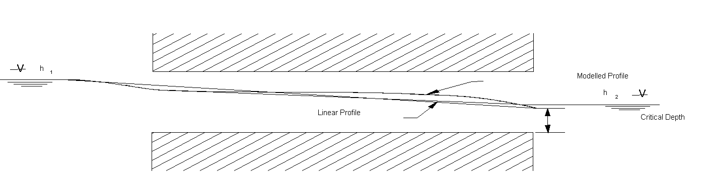
Figure: Water surface profile in the culvert at the inflow and outflow ends when the actual profile is highly non-linear.
When the outflow is close to a critical flow state the water surface profile is highly non-linear, and the friction losses calculated from a linear interpolation will be too high (the water surface profile in the culvert at the inflow and outflow ends when the). To overcome this problem without using a computationally intensive backwater analysis in each iteration, a comparison is made with the friction losses calculated from the backwater analysis for critical outflow, see above. In the case of the losses from the backwater analysis being lower, \(C_{a_{s}}\) is calculated as:
Equation: Combined headloss coefficient, expressed through the critical flow condition.
where the subscript c refers to the critical flow conditions based on h1. This also ensures a smooth transition between the outflow critical condition and submerged flow provided that z2 is less than or equal to 1.0.
The iterative procedure typically takes two to three iterations to converge. If the upstream and downstream water levels are changing rapidly more iterations are usually necessary with the number rarely exceeding ten. The maximum number of iterations is controlled by the Inter1Max variable.
In MIKE 11, the Inter1Max variable can be edited in the HD parameter editor ®Default values.
Submerged Inflow and Partially Full Outflow
This flow condition typically occurs when the culvert slope is adverse to the water surface slope as shown in the flow descriptions(h).
The iteration procedure described above is used except that the mean cross section area is adjusted according to:
Equation: Effective storage area at a structure, interpolated between the full node area and the outlet area.
where Lfull is the length of the culvert which is following full and L is the total length.
A similar adjustment is made to the mean hydraulic radius.
Partially Full Inflow and Submerged Outflow
This flow condition occurs in sloping culverts as illustrated in the flow descriptions(i). A similar procedure to that described in “Submerged Inflow and Partially Full Outflow” above is used.
Fully Submerged
Where the culvert is fully submerged (the flow descriptions(j)) the cross section areas and hydraulic radius are equal to those when the culvert is full.
Transition between Upstream and Downstream Control
Whether the flow is upstream or downstream controlled is best based on a single criterion. Using a single criterion is preferable for stability reasons and for a smooth transition between flow conditions.
Analysis of the formulations described above, assuming that z2 is less than or equal to 1.0, gives the following conclusions:
- In the case of either inflow or outflow being critical, then if H2 is below the critical water level, hc, the flow will be critical. If H2 is greater than hc then the flow can be either critical or downstream controlled. The level at which the flow becomes downstream controlled is dependent on the magnitude of z2. If z2 is equal to 1.0 the change to or from submerged flow will be at H2 equal to hc. For z2 less than 1.0, which is normally the case, downstream controlled flow will occur at some point above hc.
- Similarly, the same scenario can be shown to occur for full culvert flow and orifice flow versus fully submerged flow where hc is taken as the outflow soffit (invert plus culvert depth).
This leads to the following criteria for selecting between upstream and downstream flow controls:
- If H2 is less than either hc at outflow (critical inflow or outflow) or the downstream soffit (orifice or full culvert flow) then the flow is upstream controlled, otherwise the flow condition which gives the lower discharge is selected
In the case of critical inflow, H2 should be taken as that immediately past the point of critical flow (i.e., at the inlet of the culvert). However, for culverts of non-zero length and/or non-zero bend loss, the energy headlosses through the culvert are not known and the more conservative approach of using hc at the outflow must be taken. A similar situation applies in the case of orifice flow.