Control Structures
Control Structures differ from other structure types in two important respects:
-
the structure may be described as either an underflow structure, an overflow structure, a radial gate or a sluice gate. Thus the structure may be described as either a movable weir or a sluice gate;
-
as for dambreak structures, it is not possible to define beforehand the critical flow characteristic (Q-h) relationship of the structure.
Hydraulic aspects - radial gates
In MIKE 1D, radial gates are automatically divided into an underflow part and an overflow part.
When specifying gate levels for a radial gate, the user should specify the level for the underflow part, i.e. the level of the bottom of the gate. The gate level for the overflow part is calculated based on geometric considerations. Flow calculated through underflow part of radial gate. Calculation of the flow through the underflow part depends on the flow regime at each time step.
For free flow conditions the discharge is calculated as:
Equation: Discharge through underflow opening of control structure under free flow conditions.
where:
t is a discharge calibration factor, d is the contraction coefficient, g acceleration of gravity, y1 upstream water level, w the vertical gate opening, a the flow area through the gate (vertical gate opening multiplied with the width of the gate) and
The contraction coefficient, d, is computed as:
Equation: Contraction coefficient for flow through an inclined gate as function of gate angle.
Where q is the inclination angle of the gate relative to the canal bottom.
For submerged flow conditions the discharge is calculated as:
Equation: Submerged gate discharge accounting for contraction and head differential.
where y2 is the downstream water level.
Determination of actual flow regime is made at each time step of the simulation using the user defined parameters; ‘Tran.Bottom’ and ‘Tran.Depth’ (specified in the Graphical Interface for Radial Gate structures).
Free flow occurs if: y2 < y~Limit ~+ yTran,Bottom
Submerged flow occurs if: y~2 ~> yLimit + yTran,Bottom + yTran,Depth.
Limiting level, yLimit is calculated as:
Equation: Limiting water depth at control structure outlet for transition to submerged flow.
where H is the upstream energy head.
In the transition zone between free flow and submerged flow the discharge is calculated by using linear interpolation between the discharge through underflow opening of control structure under free flow and the submerged gate discharge accounting for contraction and head differential. Flow calculated above the Radial gate top level. If upstream water level is higher than the top of the radial gate then water flows above the radial gate. The over flow is calculated as a function of the downstream water level conditions:
When downstream water level is lower than the top of the radial gate, the discharge is calculated using:
Equation: Weir-type overflow discharge over radial gate.
where
b is the width of the gate, a and b are user defined coefficients (‘Weir Coeff’ and ‘Weir Exp’).
When the downstream water level is above the top of the gate the discharge is calculated using:
\(Q_{Overflow} = b\alpha y_1^{\beta}\left[1 - \left(\frac{y_2}{y_1}\right)^{\beta}\right]^{0.385}\)
Hydraulic aspects - sluice gates
Sluice gates are physically similar to underflow gates.
The ‘Sluice, Formula’ type of gate is an underflow gate for which four different flow regimes exist. Each of these four flow regimes are described with its own equation defining the discharge across the spillway. In addition to the flow beneath the gate an 'over-the-top' flow is added to the solution.This happens when the upstream water level exceeds the top of the gate. The active flow regime in a given situation is determined by the values of up- and downstream water level and the gate position. The different flow regimes and when they apply are listed in the flow regimes and when they apply.
Table: Flow regimes and when they apply.
| Flow Condition | Equation | Restriction | Remarks |
|---|---|---|---|
| Controlled Submerged (CS) | \(y_c = aG_0\left(\frac{H - h}{G_0}\right)^b\) \(Q = L\sqrt{gy_{c}^{3}}\) | \(\frac{h}{G_0} \geq 1.0\) | Also known as submerged orifice |
| Controlled Free (CF) | \(y_c = a G_0 \left( \frac{H}{G_0} \right)^{b}\) \(Q = L\sqrt{gy_{c}^{3}}\) | \(\left(\frac{h}{G_0} \geq 1.0\right) \& \left(\frac{H}{G_0} \geq \frac{1}{K}\right)\) \(\epsilon -\frac{1}{\epsilon}\) | Also known as free orifice |
| Uncontrolled Submerged (US) | \(y_{c}=a H\bigg(1-\frac{h}{H_{0}}\bigg)^{\vartheta}\) \(Q = L\sqrt{gy_{c}^{3}}\) | \(\frac{h}{G_{0}}<1.0,\frac{H}{G_{0}}\!<\frac{1}{K},~\&\frac{h}{H}\!\geq\!K\) \(\epsilon -\frac{1}{\epsilon}\) | Also known as submerged weir |
| Uncontrolled Free (UF) | \(y_{c} = aH\) \(Q = L\sqrt{gy_{c}^{3}}\) | \(\frac{h}{G_{0}}<1.0,\frac{H}{G_{0}}\!<\frac{1}{K},~\&\frac{h}{H}\!\geq\!K\) \(K = \frac{2}{3}\) | Also known as free weir |
| Over-the-top | \(Q = L\sqrt{gy_{c}^{3}}\) \(y_{c}=a(H-H G-G_{0})\) | \(H\!>\!(H G+G_{0})\) | Computed as a free weir flow |
H is the upstream water level measured above the sill level, h downstream water level measured above the sill level, g the acceleration of gravity, \(G_{0}\) the gate opening, Hg the height of the gate, L the spill way width, \(y_{c}\) the critical depth and Q the discharge. H, Hg, h and \(G_{0}\) are shown in sketch below.
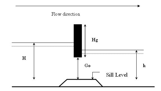
Figure: Sketch of sluice gate.
In order to avoid instabilities due to too sharp limits between the different flow regimes it is possible to define an interval across which the solution varies from one flow type to another. This is done using the 'High Limit' and 'Low Limit' option supplied in the user interface.
Hydraulic aspects - overflow structures
The calculation of the discharge over a movable weir is identical to that of dambreak structures, i.e. a broad crested weir. The only difference is that the structure width is assumed to remain constant for control and structures.
Hydraulic aspects - underflow structures
The type of underflow structures considered in the control structure operation are rectangular in shape, with a vertical sliding or rotating section. The gate will only have a controlling influence on the flow if the gate level is lower than the upstream water level. If this is not the case, the discharge will be calculated assuming an overflow structure where crest level is taken as sill level, as described above.
If the upstream water level is higher than the gate level, the presence of the gate will force the passing water into a jet, the height of which is less than the gate height due to a severe convergence of streamlines just upstream of the gate. At the point of maximum contraction, called the ‘vena contracta’, the streamlines are once again parallel to the bed, and a hydrostatic pressure distribution may be assumed to occur here, see the flow under a vertical sluice gate
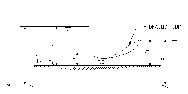
Figure: Flow under a vertical sluice gate.
This contraction of the flow may cause the formation of supercritical flow in the region of the issuing jet. Should this occur in a channel with a high tail water level, a hydraulic jump may occur downstream of the gate. In either case, the discharge through the gate will be a function of the gate geometry and upstream water level only. This is termed free discharge.
As the tail water rises, the hydraulic jump moves upstream, towards the gate. When the jump reaches the gate, it will completely drown the supercritical jet, and the water level at this point will suddenly rise to the tail water depth. The change in flow at this instant is discontinuous, due to the discontinuous nature of the hydraulic jump itself. At the discontinuity, the discharge will suddenly decrease, and may only increase if the water level upstream of the gate also increases.
The minimum downstream water level at which the hydraulic jump is drowned may be calculated from the hydraulic jump equation:
Equation: Sequent depth after hydraulic jump computed from upstream Froude number.
where, ys and y2 are the water depths (measured above the sill) at the vena contracta and immediately downstream respectively and F is the Froude number corresponding to ys.
Free flow
For a freely issuing jet (ie.not drowned), the gate discharge is a function of the gate geometry and upstream water level only. The magnitude of the discharge for a given opening will depend on the amount of contraction the jet experiences. The contraction coefficient, Cc, is a measure of this, and is defined as:
Equation: Contraction coefficient relating jet contraction to gate opening.
The contraction coefficient is dependent on the gate type: for a vertical sluice gate, Cc is in the region 0.61 - 0.63, whereas for a radial gate, the contraction coefficient is dependent on the gate level. The contraction coefficient is in MIKE 1D is an input variable and is by default equal to 0.63.
Head losses across the structure are calculated from the standard MIKE 1D descriptions via the user defined values zin and zout.
The inflow head loss is assumed to occur in the region of accelerating flow between the point upstream of the gate and the vena contracta. It would be expected to have a value between 0.0 and 0.50. The outflow head loss occurs in the region of flow expansion, between the vena contracta and the next downstream h point. Theoretical values of between 0.8 and 1.0 have been calculated for vertical sluice gates, but in practice they can be considerably higher (2).
If the flow is determined as free, the energy equation may be applied between the point upstream of the structure and the vena contracta, to yield the free discharge through the gate. Assuming, as in most cases, a zero inflow head loss, it can be shown that this equation is equivalent to the generally accepted form of the vertical sluice equation (1):
Equation: Discharge through vertical sluice gate opening using effective discharge coefficient.
where, b is the gate width and Cd is the effective discharge coefficient, calculated from:
Equation: Effective discharge coefficient for free gate flow combining contraction and head loss effects.
Drowned flow
If drowned discharge is detected, the energy equation is applied between points upstream and downstream of the structure. Note that in calculating the energy losses, the existence of a ‘submerged´ vena contracta is assumed, overlaid by a body of still water. The energy equation in this form corresponds to the submerged orifice equation of the form:
Equation: Submerged orifice discharge relating flow rate to upstream and downstream water elevations.
where Cd is the effective discharge coefficient and h1 and h2 are upstream and downstream water elevations respectively.
As mentioned previously, the change between free and submerged flow is discontinuous in nature, the free discharge being greater than the corresponding drowned discharge for the same water levels and gate opening. Such discontinuities will present numerical problems during a computation which may lead to instabilities and eventual termination of the computation. Hence, a coefficient, y, has been introduced in order to make a smooth transition. By use of this coefficient it is possible to expand the transition zone from free flow to drowned flow. The transition zone is defined as:
Equation: Transition zone bounds between free flow and drowned flow at a structure.
When downstream water level, y2, is within this interval the discharge through the structure will be calculated using an interpolation between the free flow equation and the drowned flow equation. The value of y can be set in the Mike11.ini file placed in the windows directory. The default value is zero corresponding to a discontinuity when changing from free flow to drowned flow. The user should only change this value if instabilities are encountered during the simulation. A rule is that the value of y should be as low as possible. A first guess at the value of y could be 0.01