Orifice with Gate
The orifice is a very versatile structure. It describes flow through arbitrary shaped openings and handles transitions between different flow regimes.
A controlled gate can be included in the description. A gate is one or more polygons that cover the openings defined by the orifice polygons. The position and angles in three dimensions of the gate polygons can be controlled.
Both orifice and gate can be arbitrary polygons.
The numerical description is based on pre-computed discharge tables. The pre-computed tables contain the discharge through a rectangular, vertical slice of the orifice for a number of gate positions and upstream and downstream water levels. The total discharge through the orifice is determined by integration of the contribution from all effective openings, for the given gate position and the given upstream and downstream water level.
Vertical contraction is incorporated in the pre-computed discharge tables. The lateral contraction is computed during pre-processing and the discharge will be adjusted accordingly.
The equations used to set up the pre-computed tables are based on energy levels.
Orifice and gate polygons
Orifice and gate polygons can be of arbitrary shape. The only restriction is that intersecting lines are not allowed (see the intersection of polygon lines as shown on the left polygon is not allowed).
Both the orifice and gate can included several openings, see
Rectangular and circular shapes are converted into polygons. Rectangular shapes are converted in the straight forward way, while circular shapes are converted into a polygon with 52 line segments that approximate a circle.
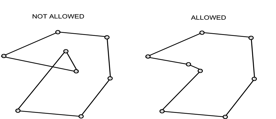
Figure: Intersection of polygon lines as shown on the left polygon is not allowed.
Definition of verticals and slices
The orifice polygon is divided into 100 equally wide verticals. A vertical covers the polygon from top to bottom. The verticals are further sub-divided into horizontal slices, where the top and the bottom of the slice are where the centre of the vertical intersects the orifice or gate polygons. See the definition of slices and verticals for an illustration of how verticals and slices are defined.
The full discharge through the orifice is found by integrating the discharge through all open slices of the verticals.
The definition of verticals is analogous for orifice and gate polygons.
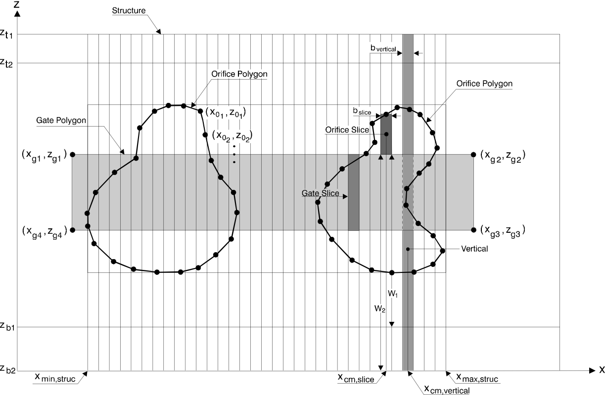
Figure: Definition of slices and verticals.
It is important to note that the verticals cover the orifice without regard to local geometry. If, for instance, the orifice has a very wide top and a narrow bottom, and the water levels are such that the discharge is primarily in the narrow lower section of the orifice, then a situation can occur where the discharge is calculated based on only a few effective slices. In such situations, the orifice might not provide an accurate approximation of the flow dynamics.
Geometrical factors that determine the discharge through a slice
The discharge through a slice depends on: 1) the width and height of the slice, 2) the height of the crest level above the upstream cross section, and 3) the height of the crest level above the downstream cross section.
The width and height are simply determined from the geometry of the slice.
The height above the up- and downstream cross sections is more complex to determine. since they require the precise geometry of up- and downstream cross sections.
The bottom is considered to be horizontal from the upstream cross section to the orifice and from the orifice to the downstream cross section. The upstream weir crest is accordingly derived as the difference between the sill level for the orifice and the bottom level of the upstream cross section. Similar is the downstream weir crest given as the difference between the sill level of the orifice and the bottom level of the downstream cross section.
It is not enough to know the shape of the up- and downstream cross sections. The relative placement of the cross sections with respect to the orifice is also important.
By default, the cross section will be placed so that the centre of the cross section is aligned with the centre of the orifice. The placement of the cross sections can be controlled with the \(L_{1}\) and \(L_{2}\) parameters. See the centring of cross sections with respect to the orifice.
If the cross sections block parts of the orifice openings, then a warning till be issued.
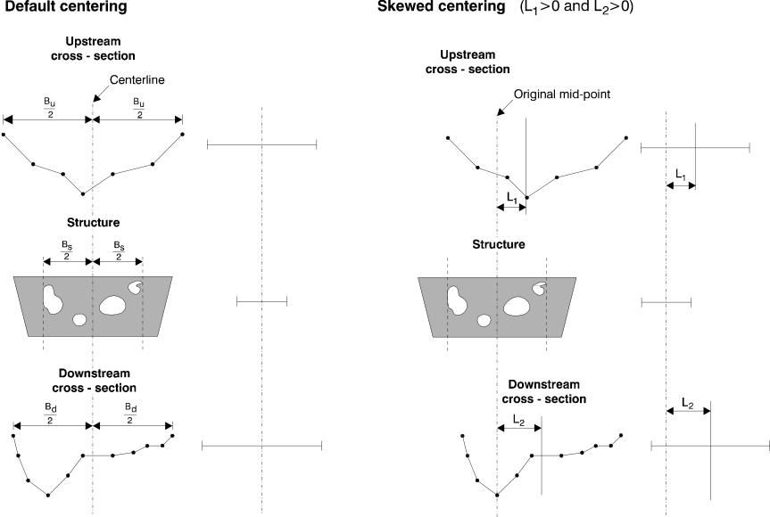
Figure: Centring of cross sections with respect to the orifice.
It is important to realise that the orifice model, although it is detailed, still has short comings:
-
The effect of lateral flow contractions may not be represented correctly.
-
The effects of Coriolis energy coefficient may affect the discharge through the orifice, but is not included.
Calculating the discharge through a slice
There are four different type of flow regimes (supercritical flow excluded). The flow regimes are classified as: 1) free overflow, 2) submerged overflow, 3) free underflow and 4) submerged underflow. A definition sketch of the four types of flow regimes are shown in the classification of flow regimes.
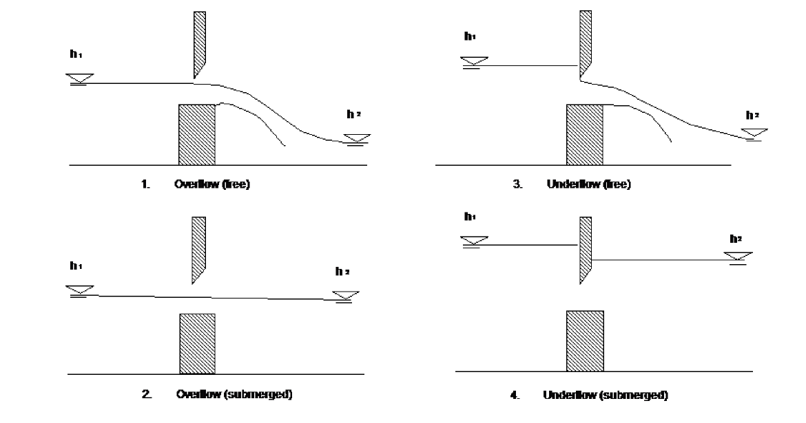
Figure: Classification of flow regimes.
Depending on local conditions, several types of jets over the weir can be observed within these four types of flow regimes. The jet types can be classified as:
-
Ventilated jet
-
Pressurised jet
-
Lifted jet
-
Adhesive jet (with water filled head, with partly water filled and partly air filled head, and with air filled head)
-
Jet filled with rolling water underneath.
An illustration of these five types of jets are shown in the classification of jet types for free flow for the free flow case.
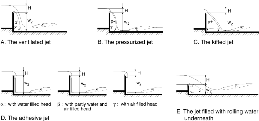
Figure: Classification of jet types for free flow.
In reality each of these five jets can occur for every of the four different flow regimes i.e. all together 20 combinations. A detailed description of these different jet types and the conditions under which they occur can be found in 1, pp 86-91.
In order to simplify the orifice, equations for the ventilated jet (case 1) for the free flow and the momentum equation for a filled jet (case 5) for the submerged case has been adopted, since these types are the most common. Furthermore a simplified correction for the downstream pressure is included.
Supercritical flow has not been considered.
Each of the supported flow regimes and jet types are described with standard flow equations, with a choice of methods and parameters that ensures a smooth transition between flow regimes.
-
Bretting, A.E: Hydraulik, Stationære strømninger, B Stougaard Jensen, Copenhagen, Denmark, 1960. ↩