Lateral links
For lateral links, the flow from the river model goes via a lateral boundary, which is then applied onto the 2D surface model. The following is true for lateral links:
- Flow through the link is dependent upon a weir equation and the water levels in the 1D and 2D model.
- Flow through the link is distributed into the 1D computational points (water level points also known as H-points) and several surface model element faces.
- The lateral links do not guarantee momentum conservation in the case of 2D flows crossing a river channel.
A basic lateral coupling structure is required to calculate the flow between the 1D model and the 2D surface model. This lateral coupling structure is typically a weir that represents overtopping of a riverbank or levee with a maximum length so to keep the highest computational efficiency (the larger the weir is, the less number of weirs will be used, and therefore faster computational speed, due to less operations to compute). The geometry of the coupling structure can be determined from cross section bank markers, 2D surface topographical levels, a combination of the highest of each, or from an external file.
For a lateral link, a special discretization of the river extension of the lateral link into short lateral coupling structures is performed. This discretization is performed as a combination of a discretization of each side, the river side and surface side adjacent to the lateral link. The river discretization consists of a division of the lateral link river extension into a series of internal river sections. Each river section corresponds to an H-point in the extension of the lateral link, and it extends until the next Q point (halfway between two H-points), or the limit of the lateral link – whichever one is closer. For an explanation of computational discretization of rivers into H- and Q- points, please refer to the MIKE 1D reference manual.
The discretization of river sections along a lateral link provides a conceptual diagram of the discretization of a river lateral link around H-points.
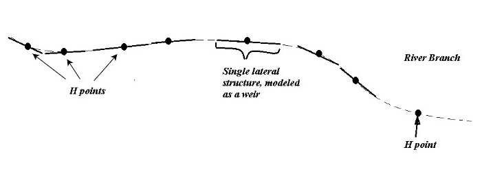
Figure: Discretization of river sections along a lateral link.
The 2D model element faces along a lateral link provides a conceptual diagram of 2D model elements along a lateral link.
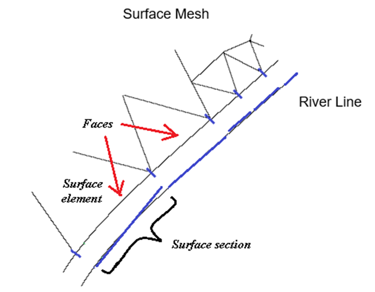
Figure: 2D model element faces along a lateral link.
Information from the 1D and 2D models is then combined to parameterize lateral coupling structures. The lateral coupling structures have bed levels and widths determined from the resolution of the river and 2D surface discretization defined along the lateral link. The resulting structures are defined such that each structure represents at most one river section and opposing 2D element face. The discretization is outlined conceptually in the lateral link coupling structure discretization.
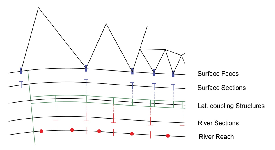
Figure: Lateral link coupling structure discretization.
During computation, each lateral coupling structure is assigned two water levels, one from the river model and one from the surface model. These values are found by interpolating levels at existing calculation points in both river and surface. The discharge value for each lateral coupling structure depends on the relative comparison between the water levels of each side, and it is calculated according to the structure type parameter as Q = structureType(\(h1D\), \(h2D\)), where structureType can be either 1) Villemonte weir, or 2) Honma weir. The discharge through the riverbank structure is computed following the corresponding weir equation.
The calculation sequence at a Lateral link provides a conceptual diagram of the calculation sequence.
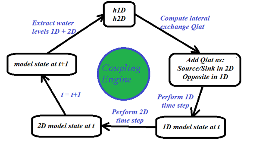
Figure: Conceptual diagram of the calculation sequence at a Lateral link.
Using the calculated width, bed level and interpolated water levels, the flow across each lateral coupling structure is computed. The flow structure is then distributed to/from the river H-points and the surface faces. This is done by determining the range of influence that a given internal structure has upon each linked river H-point and surface model face. As shown in the lateral link coupling structure discretization, if river H-points lie within the range of influence of a given coupling structure, flow is distributed across those points according to water depths in each point. The same applies for the corresponding surface element faces. It is important to note that each section related to a lateral coupling structure is associated to one and only one H-point (even if the H-point lies outside of the link extension), and to one and only one element face. Therefore, it will have one and only one water level for surface and river models, and thus the lateral coupling structure discharge can always be computed.
This approach allows for a high level of flexibility when designing the lateral link. It is, however, expected that a similar and uniform distribution of river H-points and surface faces will produce the most accurate solution. This is because when a riverbank link is set up, in principle we don't know where there will be a higher flow of exchange, so a uniform distribution of points will be safer in terms of computational precision. If the locations of the exchange were known beforehand the computational discretization could be concentrated around these areas, but unfortunately this information is unavailable a priori.
Definition of riverbank linkage lines
When a lateral link is created, the coupling module must select the exact location of the interface between the river and surface models. The critical part is the selection of the surface faces, depending on the side of the lateral link, and the chainage limits. The automated face selection process uses either the centre, left levee or right levee line. The face selection only varies in the way the line is defined. The centre line is defined through the digitised points in the river setup. The construction of the levee lines follows through several fully automated steps (see the position of a levee line).
- The cross sections located within the user selected reach are placed according to either the geo-referenced coordinates or the chainage. The latter only if the coordinates are not present or applied.
- If the cross sections are placed according to the chainage (not geo-referenced), then the distance from the centre line depends on the location of markers 1, 2, and 3. If these markers are not present, they are determined from the raw data with marker 2 normally being the lowest value (at the centre line) and markers 1 and 3 being the first and last point of the cross section, respectively.
- If cross sections are not present at the end points of the user defined reach, then the widths are extrapolated from existing cross section information at the closest location(s) in the same reach.
- For all digitised points without a cross section the width is interpolated from the existing neighbouring cross sections.
- The interpolated widths are placed so that they bisect the angle between the two adjoining line segments.
- The levee lines are thus made up by joining the respective left or right end points of the combined interpolated widths and cross sections.
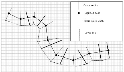
Figure: Position of a levee line in relation to the center line and cross section.
Automated face selection
The linkage lines are the lines describing the physical location of the water exchange in the surface model, and therefore the line location of the lateral inflows/sinks due to riverbank link exchange. It is important to mention that the individual elements to be coupled are identified at run time and therefore, the linkage line is independent of the element size. The linkage is made up of the coordinates of the end points of the line segments making up the linkage line. At run time the linkage line is mapped onto the element faces.