Specification of Nodes
In the specification of the network, all nodes need not be specified. If a reach is missing a node, nodes will automatically be added by the engine during initialisation.
- At network boundaries that do not have a node specified, MIKE 1D will create a boundary node.
- If two or more reaches connect at a location, and no node exist at that location, MIKE 1D will create a junction node at that location.
A junction node needs no further specification than its location. For nodes with a volume, further information on the geometry of the node must be specified, as described below.
Circular manholes
A circular manhole is a vertical cylinder, defined by the following parameters:
Hb : Bottom level, called invert level on the manhole. Hg : Ground level. Dia :Diameter Hc : Critical level.
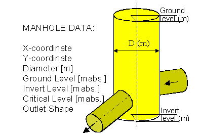
Figure: Manhole.
A manhole can add headloss to the flow calculations, see Headloss in Nodesfor details.
Behaviour for levels above the ground level is defined by the cover type, see Cover type for details.
Each manhole can have its own critical level. If the water level in a manhole increases above the critical level, then a warning is issued. This is the only use of the critical level; the value of the critical level has no influence on the result of the simulation.
This node type is not supported by MIKE 11.
Basins
This type of node is associated with arbitrarily shaped structures of significant volume: Non-circular manholes, tanks, reservoirs, basins and natural ponds.
The geometry is parametrised and defined by a table of water levels H, and associated cross sectional flow areas Afl and surface areas As.
The first set of values in the table corresponds to the bottom of the basin, and the last set of values corresponds to the ground level. Intermediate values are linearly interpolated. The H-column can start at any value, for example 0.0 for the interpretation of H as the depth in the basin. The engine will associate the first H-value to the bottom level of the node.
The basin volume contributes to the overall system volume and is included in the computations.
A basin can add headloss to the flow calculations, see Headloss in Nodes for details.
Behaviour for levels above the ground level is defined by the cover type, see Cover type for details.
This node type is not supported by MIKE 11.
Outlets
Outlets are nodes where the system interacts with external waters. The external water volume is assumed to be so large that the outlet water level is not affected by the outflow from/inflow to the system. As such, outlets are appropriate for the simulation of flow recipients and sources (lakes and oceans).
Depending on flow conditions at the outlet, both inflow and outflow can occur.
Outlets are defined with the following parameters
Hb : Bottom level. Hg : Ground level. Only used for presentation purposes.
If the reach connected to the outlet defines a bottom level, the bottom level in the outlet must match the bottom level of the reach.
The water level at an outlet is specified as a boundary condition and can take any form of a boundary source (constant, periodic, time series), see Section Open Boundary Conditions for details.
MIKE 11 does not allow the editing of ground levels of its outlets. The ground level is set to be the bottom level of the reach connected to the outlet.
Cover types
If the water level exceeds the ground level of a node Hg, then 1D engine applies one of three different covers that provides methods for handling the water:
-
Expanding cover creates a wide circular inundation basin that starts 0.25m below ground level and expands exponentially to 1000 times the surface area of the node. See Expanding node covers in the Appendix for details.
-
Sealed cover creates a narrow slot that starts 0.25m below ground level. The slot contracts gradually and in effect prevents water flowing out of the node. See Sealed nodes in the Appendix for details.
-
Spilling cover creates a free overflow at a given distance above ground level (this distance is called the buffer pressure). The width of the crest expands exponentially, which ensures that the water level never rises very high above the crest level. See Section [Spilling nodes(../MIKE1D_Appendix/Spilling_Nodes.md) in the Appendix for details.
Maximum rainfall runoff inflow
In MIKE+ (Collection System), a maximum inflow can be specified for a node. The idea is that the physical size of a manhole limits how much water can flow into the node. Because of this definition, MIKE+ (Collection System) (and MIKE 1D) applies the maximum inflow to surface water only, and therefore be extension only water from rainfall runoff.
If a maximum inflow is specified for a node, then any excessive water will collect in a pool at the node and be released in sub-sequent time steps when the inflow falls below the maximum inflow. This means that if the maximum inflow from rainfall runoff is exceeded, then the inflow to the node will be limited to the maximum inflow, and remain at the maximum inflow until all the water from the boundary has run into the node.